
This section describes the process of building a complete HO scale raceway. Suggestions and construction tips found in other sections of this web site are incorporated here, along with photographs of each phase of the construction. This particular raceway was built for a customer in nearby Chicago.
The Table
The table for this raceway is my standard 4×8 foot plywood table with 1×4 framing and 4×4 legs. It is the same design as described in the Tables section. The other table sizes described there use the same construction principles as the table illustrated here. Simply extend the length and width if you will be building one of the larger tables described there.
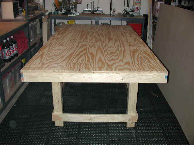
The photograph below shows the completed 1×4 frame and 4×4 leg assembly prior to mounting the plywood top and Homasote sound damping material. All frame joints are glued and fastened using No. 8 wood screws.
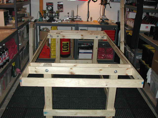
The 4×4 legs are attached to the table frame cross bracing using 6″ long 3/8″ bolts, fender washers and wing nuts. The 4×4 legs however are not glued to the upper table frame. This allows the table top to be removed from the 4×4 leg assembly for easier transport and storage.
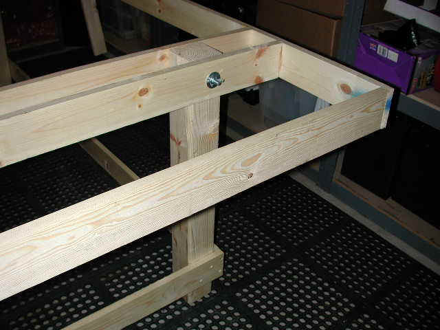
The picture below illustrates the cantilever construction principle I use to reduce load bearing spans and increase the table’s overall rigidity.
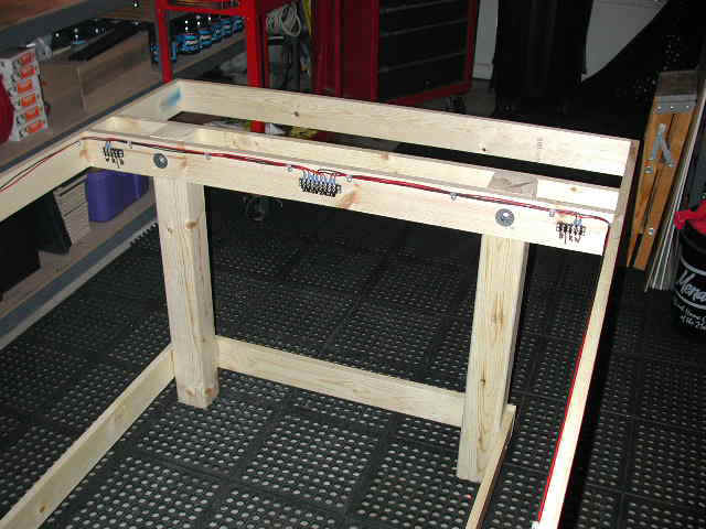
Most of the track wiring is installed before the plywood top is attached. This produces a neater wiring job, and reduces the amount of work that must be carried out lying on my back, or with the table turned on its side. See the Power section for wiring schematics, or the Track Wiring Kits section to purchase a complete Fused 4-Lane Track Wiring Kit. My track wiring kits include complete step-by-step instructions and do not require any soldering or prior electrical experience to install.
On smaller tables such as this 4×8 footer it’s often better to place two drivers stations along each of the longer 8 foot sides of the table. The 8-position barrier terminal block mounted in the center of the cross brace is where track power will be applied to the table. The smaller barrier terminal blocks flanking it on either side are for drivers station hookups.
I normally design my smaller raceways with the drivers stations for lanes 1 and 2 along one side of the table, and lanes 3 and 4 along the other side. The drivers stations for the center lanes, 2 and 3 are mounted on opposites sides and at opposite ends of the table. This arrangement allows for just 2 racers running on lanes 2 and 3 to easily marshal the entire raceway with a minimum of movement.
The next step of construction involves applying the plywood table top. A single 4×8 foot sheet of ¾” A/B grade plywood was selected. The edge of the 1×4 frame was coated with Elmer’s Exterior Wood Glue before attaching the plywood sheet. While this particular table was built using ¾” plywood, thinner ½” plywood can be substituted.
With the plywood sheet in place the table top can now be fastened to the 1×4 frame using 2″ No. 8 Flathead Wood Screws. The table top is fastened to the outside table frame as well as the supporting cross braces. Screws are placed at 1 foot intervals to securely fasten the plywood to the frame and make a strong, rigid table top.
Important: Drill pilot holes for all No. 8 wood screws. Do not just use deck screws and a power driver, unless you want a table frame that splits. Special countersinking bits for wood screws are inexpensive and will make perfect pilot holes every time. In a pinch you can use a 1/8″ drill bit if you don’t have a countersinking bit available.
Note the screws used to fasten the plywood sheet to both the outer edges of the table frame as well as the two parallel cross braces used to mount the table’s legs.
With the plywood glued and fastened to the frame with screws, all that remains is the Homasote sound damping layer. The Homasote will be painted green in a later step to replicate turf. No fasteners are used here. The Homasote is bonded to the plywood table top using only glue. Heavy weights can be placed on the table top to hold the Homasote in place while the glue dries.
Now it’s time to fill the exposed screw holes on the sides of the table frame and legs with wood filler, then sand and prime the bare wood. The entire table is primed including the Homasote top, sidewalls and leg assembly. I use Kilz Original Oil-Based Sealer. It covers well and dries quickly. A good quality oil-based sealer makes later painting a much easier task. The Homasote used for the table top is very porous and requires two coats of primer to completely seal it.
With the entire table primed and sealed all that remains of the table construction phase is painting the table top, sides and leg assembly. The legs are painted with a dark gray enamel, the retaining walls are painted with white enamel and the table top is painted using a dark shade of green to replicate turf. The picture below shows the completed table.
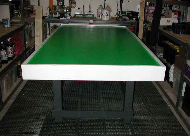
The table described above can be completed in a single weekend. Acquiring the lumber, cutting it and constructing the table itself can be done on Saturday, and the primer coat applied late that afternoon. On Sunday the entire table can then be painted and left to dry.
Here’s a complete inventory of what was required to build this 4×8 foot table.
Lumber
(1) 4×8 Sheet of ¾” A/B Exterior Grade Plywood
(1) 4×8 Sheet of ½” Homasote Sound Board
(8) 1×4 – 8 Foot Lengths of Dimensional Lumber
(2) 1×8 – 8 Foot Lengths of Dimensional Lumber†
(2) 1×8 – 6 Foot Lengths of Dimensional Lumber†
(2) 4×4 – 8 Foot Posts Cut to 32″ Lengths‡
Hardware
(4) Threaded Leveling Feet
(1) Box of 2″ No. 8 Flathead Wood Screws
(1) Box of 1-1/4″ No. 8 Flathead Wood Screws
(4) 3/8″ Bolts 6″ in Length
(8) 3/8″ Fender Washers
(4) 3/8″ Wing Nuts
Finishing
(1) Gallon of Elmer’s Exterior Wood Glue
(1) Pint of Red Devil Wood Filler
(1) Package of 3M Sand Paper (Fine/Medium/Course)
(1) Gallon of Kilz Original Oil-Based Primer
(1) Quart of Rustoleum Dark Gray Enamel (Glossy)
(1) Quart of Rustoleum White Enamel (Glossy)
(1) Quart of Rustoleum Hunter Green Enamel (Glossy)
(4) Disposable 2″ Paint Brushes
(1) 9×12 Foot Heavy Duty Drop Cloth
Electrical Wiring
(4) 4-Position Barrier Terminal Blocks
(3) 8-Position Barrier Terminal Blocks
(28) 3/4″ No. 6 Wood Screws
(50) Feet of Black 16 Gauge Stranded Wire
(50) Feet of Red 16 Gauge Stranded Wire
(48) 14 Gauge No. 6 Spade Lugs
1×8 inch dimensional lumber should be used for the side retaining walls. The table pictured above used 1×6 inch lumber, but that was only because the customer requested it.
If younger children will be racing, you may want to reduce the table leg heights to 26-28 inches.
Some of the more specialized Track Building Supplies listed above may be hard to find locally. You can order them directly from me.
The Track
The layout selected for this project is my standard 4×8 foot 4-lane raceway built entirely from Tomy AFX track sections. It provides a fast lap with a challenging infield section. This is the same raceway that appears on the For Sale page.
This layout strikes a good compromise between speed and rhythm. Racing is done in a counter clockwise direction. The long straight on the right side of the diagram feeds into the slow-speed hairpin section. Exiting the hairpin the cars negotiate a 90 degree right-hander, gradually accelerating down the infield straight before slowing for a decreasing radius turn. A short chute follows and then it’s into the carousel section before accelerating down the back straight. A series of two high speed turns separated by another short straight lead back onto the main straight.
Here’s an inventory of the Tomy AFX track sections required to build this raceway:
Straights
28) Tomy AFX 15″ Straights
(6) Tomy AFX 9″ Straights
(8) Tomy AFX 6″ Straights
(2) Tomy AFX 3″ Straights
Curves
(1) Tomy AFX 15″ Radius 1/8 Circle Turns
(18) Tomy AFX 12″ Radius 1/8 Circle Turns
(23) Tomy AFX 9″ Radius 1/8 Circle Turns
(6) Tomy AFX 6″ Radius 1/8 Circle Turns
The picture above shows all of the track building supplies that will be used for this project. The Astron 10 Amp 0-30 VDC Variable Power Supply and Parma 45 Ohm Turbo Plus Hand Controls are shown towards the back of the table. Tomy AFX track sections, four GT Prototype Super G+Plus cars and guard rails are shown directly in front of them.
Track wiring supplies and four of my Tomy AFX 15″ Custom Power Terminal Tracks are shown on the far left side of the table. The plastic bags in the foreground contain my Fused 3-Wire Driver’s Stations and a Lap Timer 2000 Computer Interface Cable Kit including the photo-cell sensors, computer connector, software disk and CAT-5 Network cable interface.
All of the track building supplies illustrated in the picture above are available on the Power and Controller pages of this web site.
The first thing to do now is to lay the track out on the table and test the fit. The customer that this layout is being built for requested that the overall layout be flipped along the lateral axis to better fit into his room. The track configuration remains the same as the Tracker 2000 diagram above, it has simply been “flipped” to the customer’s specifications.
The layout as designed is 45 inches wide and 93 inches long. The 4×8 foot table is 48″ × 96″ which provides for a 1-½” border on all four sides of the table.
Track power will be applied at two locations around the raceway. The first power tap will be placed along the fastest straight on the left side of the diagram below, with the second power tap on the short infield straight. These two locations were selected to supply power evenly around the track. See the Power section of this web site for a complete discussion of the importance of applying power evenly around your raceway.
With the power tap positions calculated all that remains is to select the location of the start/finish line. This is where the photo-cells will be installed to count and time laps. The “flipped” layout as shown above has the cars circulating in a clockwise direction as they race.
Track Mounting
Now it’s time to begin mounting the track to the table. I like to start with the longest straight. The overall size of the track itself provides a 1-½” border on all for sides of the table. 1×4 dimensional lumber is actually ¾” when finished, so two pieces laid flat against the side of the retaining wall provide a perfect straight edge for track mounting. Track can simply be butted up against the 1-½” sandwich to assure perfect alignment.
The first section of track laid is the most important. It needs to be square with the table and properly positioned. All subsequently mounted sections will be attached to this cornerstone, so to speak, so take the extra time and make sure it’s right. I make my Custom Power Terminal Track the first section laid.
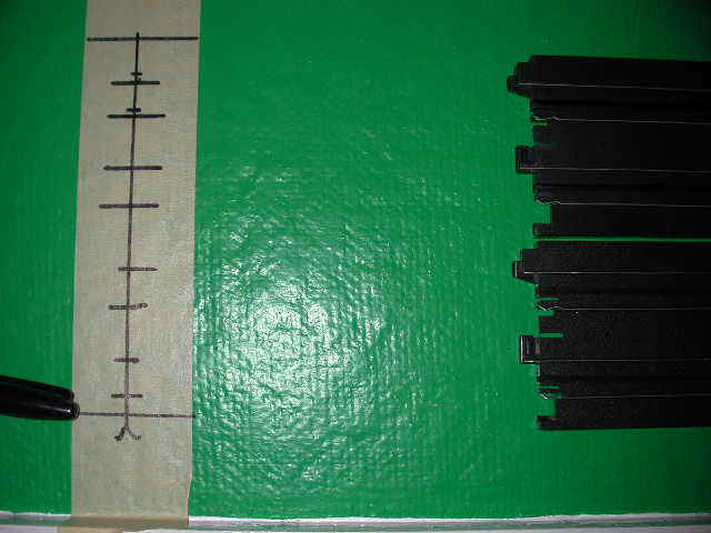
The Custom Power Terminal Tracks that I build have four (4) one-foot lengths of wire soldered to the underside rails. I use a red and black wire for each lane to make polarity connections easier. I also fit #6 spade lugs to the ends of the wires to allow for a neat and tidy hookup underneath the table.
With a piece of masking tape in place I mark the location of the holes I plan to drill. I use a 5/16″ drill bit to make holes that the #6 spade lugs will slip through. The picture below shows the marked positions on masking tape.
The picture below shows the first Custom Power Terminal Track placed in position. Note the two pieces of 1×4 dimensional lumber used to make certain that this track is mounted square with the edge of the table.
The track will be mounted to the table top using 1″ No. 3 Flathead Wood Screws. A countersunk hole is made using the track mounting nail holes found at each end of Tomy AFX track sections.
I made my countersinking tool using a standard countersinking drill bit with a ¼” shank mounted in a small machinist’s T-Handled tap wrench. Very little material needs to be removed to create the countersunk hole that the screw head will rest in, and I’ve found that mounting the countersinking bit in a power drill invariably leads to holes that are drilled to deep. A few turns of the hand tool that I use is all that’s required to make the countersunk hole the proper depth.
The picture above illustrates what the countersunk hole looks like prior to having a screw placed in it. Note the 1″ No. 3 Flathead Wood Screw directly to the left of the hole. The length of the screw that you use may differ depending upon the thickness of your table. This table has a ½” layer of Homasote sound board covering a ¾” piece of plywood.
Tomy AFX itself is just slightly over ¼” in thickness, so a 1″ screw will pass through the Homasote sound board and provide just over ×” of bite into the plywood.
No. 3 Flathead Wood Screws are available for sale on the Track page if you can’t source them locally.
WARNING: Avoid using a screw length that will allow the pointed tips of the wood screws to protrude out from the bottom side of the plywood. This is very important! You’ll be crawling around under the table to wire and having hundreds of needle-like spikes will make that phase of the project bloody and very dangerous.
I’ve found that the best results are achieved if you start by mounting an entire 2-lane portion of the track first. This will provide a solid edge for later mounting of the second 2-lane portion.
Starting from my originally mounted power terminal track I move around the raceway until the entire pair of lanes is mounted. Starting with the outside pair of lanes makes fitting the second pair of inside lanes much easier.
Pay close attention to the track joints as you work. You don’t want any large gaps between track joints that would cause the car to bounce as it passes over a joint. I normally countersink holes in 3-4 sections of track at a time and then carefully fasten them using the wood screws. Don’t fasten them down to tightly though, just enough to make a secure and flush joint.
The silver colored heads of the flathead screws can be hidden with a Sharpie Black Permanent Marking Pen. The screw heads will all but disappear when the heads are painted black. You may want to wait though until you’ve completed an entire section of track before using the marking pen. Once the heads are painted black it will be difficult to spot any missed holes that don’t have a screw securing them to the table top.
In the picture below the outer track sections that make up the hairpin turn have been fastened to the table top, but the inside pair of lanes as yet, have not. The gap between the inner and outer lanes can be minimized by later mounting the inside track sections flush with the outside pair of lanes. Note too, that the screw heads have been hidden using a Sharpie Marker.
Take your time with this phase of the track construction, and inspect each screw used to fasten the track to the table top. This particular layout is comprised of over 90 sections of track, each with two mounting holes. That’s almost 200 holes that will need to be countersunk and fastened with a screw.
You can fine-tune the joints as you work to create a smooth running track. It will take several hours to complete this phase of construction, so take your time and work slowly and methodically.
Lap Timer 2000 Installation
My Lap Timer 2000 4-Lane Interface Kit is also being installed on this track. The kit includes four (4) photo-cells that are to be placed under the track. The photo-cell leads are run to a small junction box that will be mounted under the table in a later step.
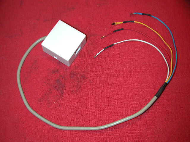
The photograph above shows the photo-cell sensor assembly and the junction box that will be mounted under the table. Standard HOPRA lane color-coding is used to simplify the installation.
HOPRA Lane Color Codes are as follows:
Lane 1 – Red
Lane 2 – White
Lane 3 – Blue
Lane 4 – Yellow
On this particular track lane 1 is the outside lane closest to the driver’s stations, while lane 4 is the inner-most lane.
See the Lap Timer section of this web site for more information about my Lap Timer 2000 Software and photo-cell wiring schematics.
Four (4) small holes will need to be drilled in the table directly beneath the track sections that will form the start/finish line. The photograph below illustrates this step. A ¼” drill can be used to make the four holes that will be required.
Once the four holes have been drilled the sensor leads can be fed up from the underside of the table. The red, lane number 1 lead is inserted in the first hole closest to the retaining wall with the remaining leads for lanes 2, 3 and 4 inserted in order after it. Remember, it’s red, white and blue, then yellow.
Small 1/8″ holes will also need to be drilled in the track itself. These holes should be drilled between the slot and the power rail. This location assures that both open-wheeled Formula 1 cars as well as full-bodied cars will break the light beam properly.
The photo-cells included in the Lap Timer 2000 sensor assembly are the small flat rectangular variety. They have a small plastic lens on one of the flat sides that needs to be placed facing up through the holes drilled in the track.
The photo sensor is a press fit between the slot and power rail extrusions, but it’s a good idea to place a dab of contact cement or use a piece of black electrical tape to hold them firmly in place.
With the photo sensors mounted and secured to the underside of the track the sections can be turned back over and inserted in the layout. The remaining track will need to be mounted to finish up the track mounting phase of construction.
Track Wiring
Now it’s time to wire the power tracks and hook up the driver’s stations. The remaining track wiring all needs to be done from under the table. If you have an automotive creeper use it. Also try to have everything you’ll need under the table with you, otherwise you’ll be forever climbing out from under the table to retrieve tools and supplies.
If you have a trouble light put a small screw eye in the underside of the table top to hang your light from. It can get dark under the table and having a good light source makes the entire wiring phase easier and go much smoother.
A second option, if your table is not too large or too heavy, is to have someone help you turn the table on it’s side. Be careful though and get a friend to help. Even a 4×8 foot table can get pretty heavy once the plywood table top has been attached. Protect the area where the painted retaining walls will contact the floor too. You don’t want to scratch or damage them. If you’re working alone do not try to turn the table on its side by yourself, it’s just too heavy and you’ll end up dropping it and cracking the retaining walls.
I start by mounting an 8-Position Barrier Terminal Block near each of my Custom Power Terminal Tracks. One wire from each lane’s power rails is connected to the corresponding barrier terminal block as pictured below. There should be a one-to-one relationship between the power rail wires and the barrier terminal block. Although the cable clamps hide this fact, the red wire protruding through the upper-most hole on the left side of the photograph is connected to the upper-most position on the barrier terminal block on the right. This relationship is maintained for the remaining wires. Failing to do this leads to all kinds of grief later when you try to figure out why a specific lane’s driver station does not seem to be controlling the correct lane.
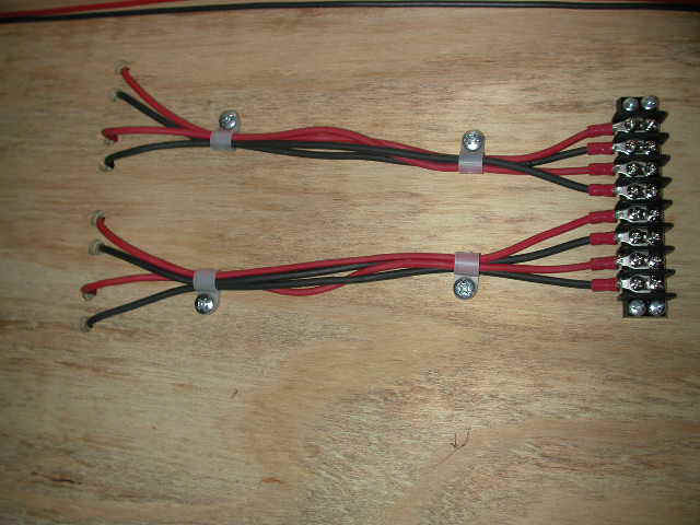
I use 1/4″ Nylon Cable Clamps to secure the wires to the table. I also use a small strip of 3″ Black Racers Tape to protect the wires at the point where the wires protrude from the track above. The adhesive used on Racer’s Tape is very sticky, but I follow up by putting a couple of staples along the edge just in case. A well-made slot car table should last 20-30 years, and I’m not sure that the adhesive alone will protect the wires for that length of time. The tape also serves to cover the holes and keep dust from entering the bottom side of the track directly above.
The Lap Timer 2000 Sensor Leads also need to be dressed and protected. Here I use 1/8″ Nylon Cable Clamps to mount the individual sensor lead wires and 3/16″ Nylon Cable Clamps to fasten the interface cable to the table.
Again I follow up with a protective layer of Racer’s Tape and staples. Be careful when you staple the Racer’s Tape in place though, you don’t want to catch the sensor leads. The photo-cell sensor leads are very small, so protecting them with a layer of Racer’s Tape is required.
The next wiring step involves running a pair of red and black wires from the driver’s station barrier terminal blocks to the track power blocks described above. You’ll recall that I attached them to the table frame before the table top was mounted to reduce the amount of work carried out lying on my back.
The picture below shows their original mounting locations. For this particular table two driver’s stations hookups are mounted at each end of the table frame on the leg support cross braces. The connection block for Lane No. 1 is located on the right side of the table cross braces in the photo below. This is the connection block I will be wiring first.
With the power track wiring mounted and secured we can now move on to the driver station hookups. A pair red and black wires are attached to the driver’s station barrier terminal block and routed to the primary power tap.
The red and black wires running from the driver’s station barrier terminal block are attached to the first two points on the block. The picture below show these same two read and black wires as they are attached to the main power tap.
The red and black wires running horizontally at the top of the picture above are coming from the Lane No. 1 driver’s station connect block. The second pair of wires running diagonally away from the primary power tap are then connected to the secondary power tap as shown below.
My Fused 4-Lane Track Wiring Kit includes the Fused 3-Wire Driver’s Stations needed to complete the track wiring phase of this project. Each Driver’s Station comes primed and ready to paint to match your track’s lane color coding. The picture below shows a driver’s station prior to painting and mounting.
The picture below shows the Lane No. 1 Driver’s Station mounted to the table frame. Four (4) holes will need to be drilled to pass the wiring and fuse block through the table’s side frame. Before final mounting, the driver’s stations will be painted to match the track’s lane color coding. Complete Track Wiring Kits and Fused 3-Wire Driver’s Stations can be ordered on the Power page.
The next picture illustrates the wires passing through the table’s frame and how they’re attached to the driver’s station terminal barrier block.
At this point I’ve completed the track wiring for Lane No. 1. Before I move on to the remaining three lanes I like to test my work. So all that remains now is to attach power wires to the main track power terminal block and connect the track’s power supply.
I test the car on Lane 1 first. Then on lanes 2, 3 and 4. If the car runs on any lane other than just Lane 1 then I know that my power tap jumpers between the main power track and the secondary one are incorrectly connected.
It’s important to perform this test with only the first lane wired. Once you know that you’ve got everything wired correctly it’s a simple task to wire the remaining three lanes.
The 4×4 posts used for the table’s legs make a good mounting point for two shelf brackets to support a small shelf under the table at the far end of the track. I used a 42″ stairway tread for the shelf. They are 1″ thick and cost only a few dollars. Heavy power supplies and a computer can be placed on this shelf without it sagging. I painted it dark gray to match the table frame’s legs . This shelf fits neatly under the table and provides a convenient spot to place the track power supply. The 42″ width of the shelf also provides enough extra room to store pit cases and other racing supplies.
The power supply shelf shown above fits entirely under the table itself and does not extend out beyond the track’s retaining walls. Its 42″ width is actually large enough to hold up to four Aston power supplies if you’ll be using individually powered lanes. You can also use the shelf to hold a computer if you want to locate it under the table and out of the way.
I used slotted metal shelf standards and movable shelf support arms to hold the power shelf. There’s actually enough room under the table to mount two shelves if you find that you need extra storage space.
Track Landscaping
The track as described above is now ready for day-to-day racing. If you would like to add authenticity to your layout though, you may want to consider landscaping. See the Landscaping section of this web site for detailed information and step-by-step instructions for creating a raceway that looks like an actual race track.