
This section will describe the process of landscaping an HO raceway. A landscaped layout requires a sturdy table. A well-made table will prevent the track and landscaping elements from flexing and possibly cracking when the table is moved or transported to another location.
See the Tables and Construction sections for more information about building a sturdy and stable platform for a landscaped raceway. The raceway I intended to build would have to fit on my standard 4×8 foot plywood table.
Landscaping a slot car track is a compromise between authenticity and utility. The race track is the main focal point, with landscaping elements added to highlight the track itself.
The German architect, Mies van der Rohe said it best, Less is more. The same approach should be taken when landscaping a slot car track. A few carefully selected landscaping elements can lend to the authentic appearance of the raceway without overpowering the overall scheme.
Instead of trying to exactly duplicate an actual raceway, it’s easier to select just a few key elements found at most raceways. A pit row and garage complex are often enough to suggest a realistic working raceway. A garage complex also provides a setting for showcasing your favorite slot cars.
Always keep in mind that you’ll be racing on your track. The drivers’ site lines need to be clear for the entire lap. Place trees and other foliage so as to allow the drivers to be able to see their cars as they move around the raceway.
Most HO model railroad landscaping materials can be adapted to slot car tracks. Turf, trees and other foliage can be used with great success. The Woodland Scenics Company is a great source for all of these landscaping materials.
Track Design and Mounting
Once a sturdy table has been built the track itself can be mounted. For this layout I choose to glue all of the track section joints and then solder the metal power rails for a smooth running, continuous rail track.
For added visual appeal I decided upon a 4-lane raceway with an overpass. Elevation changes offer a simple means of adding interest to an otherwise flat race track. An overpass also makes it easier to design a track with lane lengths that are approximately the same length.
Equal, or close to equal lane lengths does not automatically imply that all racing lanes will be of the same difficulty, but it does make it possible to more easily alternate tight inside and sweeping outer curves for lanes 1 and 4 on a 4-lane raceway.
Using Tracker 2000 layout software, I designed and tested the raceway illustrated below. This particular raceway has even lap lengths of 33.5 feet for each lane.
Before permanently mounting the track on the table, I raced on this circuit for several weeks to make sure it was exactly what I wanted. Once the track joints are glued and the power rails are soldered together it would be impossible to make any changes.
The short straight located towards the center of the table will be used for the pit access road and garage complex. This area provides a good location and just enough room to build a 6-8 stall garage with an adjoining pit lane and retaining wall.
At most modern tracks the start/finish line is located directly in front of the pit lane and garages, so photo-cells were installed along this straight as well.
The track inventory below lists the Tomy AFX track sections required to build this 4×8 foot layout.
Straights
(28) Tomy AFX 15″ Straights
(8) Tomy AFX 9″ Straights
(8) Tomy AFX 6″ Straights
Turns
(16) Tomy AFX 12″ Radius 1/8 Circle Turns
(20) Tomy AFX 9″ Radius 1/8 Circle Turns
(4) Tomy AFX 6″ Radius 1/8 Circle Turns
I started with a Tomy AFX Super International Race Set and then added the extra track required to build this layout. Unless you already have a good inventory of Tomy AFX track on hand this is the most economical way of getting all of the track needed, and you get four (4) Formula 1/IndyCar Tomy AFX Super G+Plus slot cars in the bargain. If your tastes run more towards Le Mans GTP sportscars then purchase the Tomy AFX 4-Way Split Race Set instead.
Tracker 2000 makes it easy to design slot car tracks that can actually be built. When designing a layout try to get the last remaining sections of track to align properly. Large gaps or mis-alignments will make it very difficult to build the track and mount it on a table. Try to keep these mis-alignments to less then ½”. It’s better to have the last two remaining track sections overlap slightly then to leave a gap.
Track Joints
With a raceway layout decided upon, the first task involves gluing and soldering the metal power rails. I like to assemble entire sections of the raceway on my workbench. I start by building the turns and straights as separate sections and then do the final assembly on the table.
The process of gluing, soldering and sanding the track sections can get messy, so carrying out this phase of the project on a workbench will make cleanup much easier.
Start by gluing up a 2-lane turn section. I use Plastruct Plastic Weld. This type of glue can be found in the model making department of better hobby shops. Purchase the orange label bottle if possible. In some states only a white label version is available. It works, but it’s not as good as the original orange label.
Put a drop of glue on each of the two center tabs at a track joint along with a drop in each of the two tabs on the outsides of the track. Join the two track sections and make sure the center tabs are fully locked together and flush with the surrounding track surface. Repeat this process for an entire turn.
Wipe away any access glue that might squeeze out of the joint when the track sections are joined and then set the completed turn assembly aside. Let the glue cure overnight.
The metal power rails can easily be soldered if you apply a dab of soldering flux to the rail joints before attempting to solder them. I use Soldering Flux Paste to prepare the rails for soldering. You must use soldering flux, attempting to solder bare metal rails without first applying flux will lead to many problems.
The soldering flux I use is sold in a small shoe polish-like tub. Place a dab on each of the four metal power rails that make up the joint of a 2-lane track section.
The metal power rails can be soldered if you use a hot iron. The iron should be at least 35-45 watts and should have a chisel tip. Lower wattage irons simply will not work! You need to use a soldering iron that can quickly heat the metal rails without melting the plastic on either side of the rails.
Place the chisel tip on the rails where they’re joined and apply solder to fill the gap. The flux you applied earlier will melt and flow into the joint, allowing the hot solder to fill the joint and make a good electrical connection.
Note: If you’re new to track construction then you may want to practice gluing track sections together and soldering the power rails on some scrap track sections to get the hang of it. The process is not particularly difficult, but it does take a little practice to become comfortable with this method of track construction.
Review the Soldering section for detailed information about soldering equipment and supplies needed to properly solder your track’s power rails.
Repeat this process for all of the joints that make up a complete track sub-assembly.
At this point you should have a complete 2-lane turn or straight assembly that is ready to be cleaned and sanded. I use Formula 409 Degreaser and Cleaner sprayed on a lint-free rag to clean the remaining flux from the track surface.
After cleaning the entire track surface use a piece of Medium Grit 3M Emory Cloth wrapped around a small block of wood and sand the metal rail joints. Sand the metal power rails at the points where you soldered them until they’re smooth.
Follow up by sanding the entire track surface using a Medium Grit 3M Sanding Sponge. Vigorously sand the track section assembly until the rail joints, as well as the plastic track surface is smooth to the touch.
Repeat the entire gluing, soldering and sanding process for all of the turn sections and straights that make up your layout.
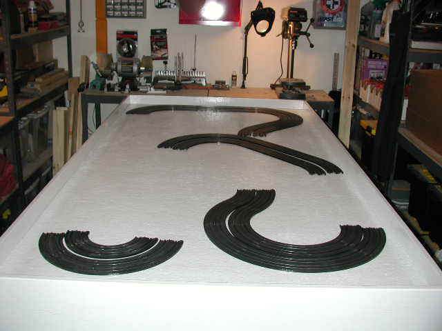
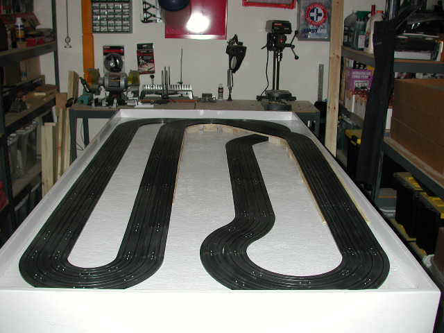
The picture below shows the eight glued and soldered turn assemblies that will make up this road course. The table that I built for this track has a ¾” plywood base with a ½” Homasote soundboard layer glued to the tabletop. The Homasote has been sealed with Kilz Oil-Based Primer, but has not been painted like the other tables I normally build because a later step will involve applying Woodland Scenics turf materials.
At this point you should have a dozen or more glued and soldered track sub-assemblies that can now be joined on the table. The remaining joints that connect the turns with the straights will need to be glued and soldered on the table to complete the assembly process.
Finish up by sanding the few remaining rail joints to complete this phase of the track building process. You should have a smooth running, continuous rail raceway at this point. The time and effort spent preparing the track joints will make for a raceway that will never suffer from mysterious electrical gremlins or bumpy track joints and slots that can catch the guide pin.
Track Geometry
Anyone who has ever built and mounted a Tomy AFX 4-lane raceway will tell you that the inner and outer 2-lane plastic track sections do not fit together properly. While Tomy AFX track sections are designed to nest inside of one another to create 4, 6 and 8-lane raceways, there is actually a 1/8″ gap between the 2-lane track sections.
To prove this to yourself, assemble four (4) Tomy AFX 12″ Radius 1/8 Circle turn sections to form a 180 degree turn. Now do the same thing with four (4) Tomy AFX 9″ Radius 1/8 Circle turn sections. Keeping the joints tight and square, place the 9″ turn assembly inside of the 12″ turn. Notice that with the track sections properly joined there will be a 1/8″ gap between the two turn assemblies. This is normal, and can not be avoided.
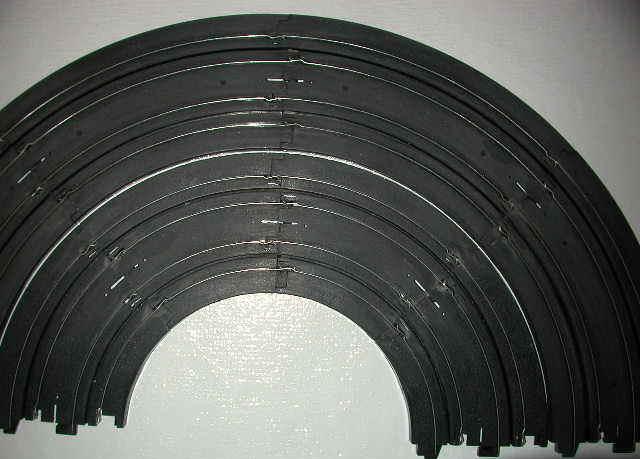
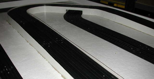
The picture below illustrates this gap. 6″ and 9″ glued and soldered hairpin section are shown together. Note the 1/8″ gap separating the two corner assemblies.
The process of gluing and soldering the power rails, as described earlier, means that once you assemble the entire track on the table this gap will be evident in several locations around the circuit.
To balance the gap and to keep it consistent around the track I normally place small strips of 1/8″ cardboard between the 2-lane sections to maintain an even gap while mounting the track on the table.
This gap between the separate 2-lane sections will be filled later after the track has been secured to the tabletop.
Track Elevation
Once all of the track sections have been joined on the table it’s time to actually fasten them to the tabletop. Use 1 Inch No. 3 Flathead Wood Screws in countersunk mounting holes as described in the Construction section. Fasten all track sections to the tabletop, except for those that will be elevated.
With the track assembled and fastened to the table top the next step involves building the elevated section of the layout. Cut a U-shaped section of ¼” plywood to support the elevated portion of the raceway. You can use the track itself as the template and trace around the inside and outside edges with a pencil. Then cut along this pencil line using a jigsaw.
The straight leading up to the bridge on the right edge of the table will have a ¾” space between the track’s edge and the table’s retaining wall. Leave this area of the plywood flush with the retaining wall. This will make cutting and later repositioning the plywood an easy task.
The picture above shows the track with the elevated bridge section towards the far end of the table. I used 2×4 lumber laid on it side to create the level portions of the bridge and 1×4 lumber for the supporting ramps leading up to the bridge. Use 1-1/2 Inch No. 8 Wood Screws and Elmer’s Wood Glue to fasten the plywood bridge section to the 2×4 lumber. Use 1 Inch No. 8 Wood Screws to secure the 1×4 lumber to the plywood ramp.
Position the 2×4 lumber under the plywood so that it lies directly beneath the track mounting holes. That way you’ll be able to secure the track using 1 Inch No. 3 Wood Screws that pass through the ¼” plywood and fasten securely into the 2×4 lumber underneath.
Note Keep in mind that you’ll be fastening the track to this assembly later, so keep the screws that secure the plywood to the supports clear of the area where the track mounting screws will be used.
Follow up by using 2-3/4 Inch No. 8 Wood Screws driven up through the bottom of the table to secure the 2×4 supports to the table itself. Some Elmer’s Wood Glue applied to the bottom surfaces of the wooden supports will keep them secured to the tabletop.
The picture below shows 1×4 lumber, also laid on its side to form the ramp leading up to the bridge section. This support is also positioned directly beneath the track mounting holes to provide a good solid piece of wood to hold the track mounting screws. Use 2-1/4 Inch No. 8 Wood Screws to secure these supports from the underside of the table.
The 2×4 and 1×4 lumber used to support the ¼” plywood should be cut so that it’s the same width as the plywood ramp itself.
Note also that the plywood ramp extends beyond the next pair of track mounting holes and extends halfway along the final 15″ straight. This provides an even, gentle rise. The final straight section is secured to the plywood ramp on the left and directly into the table on the right.
Retaining Walls
The sides of the evaluated portion of the track can now be enclosed to hide the plywood bridge and its supports. Vinyl 4″ Cove Molding works well for this. It can be easily formed to follow the contour of the evaluated track section and can be cut with a simple pair of scissors. Vinyl molding is available in 4 foot sections or as continuous 20 feet rolls. Purchase Cove Molding that does NOT have pre-applied adhesive.
The back side of this material has horizontally molded grooves that can be used as a cutting guide. Start by removing the lower quarter round by cutting about ½” inch of material from the lower section of the entire length. Repeat this process for the upper edge as well. Measure the height from the table top to the track surface and then add ½” to form the guard rail.
The rising slope of the track itself can be used as a guide for marking the line you’ll need to cut along to form the ramps leading up to and away from the bridge. A small scrap of ½” plywood placed under your pencil makes an ideal gauge for marking the sloping line you’ll be cutting along.
Place the molding you’ve just cut into position and mark the area where the track runs under the bridge. Make two vertical cuts to form the bridge opening and then make a horizontal cut to remove that section.
Apply a bead of Liquid Nails Construction Adhesive to the edge of the plywood, the 2×4 and 1×4 bridge supports and along a line on the table where the lower edge of the molding will contact the table top.
The bead of adhesive you apply to the table top will hold the molding in place, and will be concealed in a future phase of the construction. Small 1″ Nails can be driven through the molding itself and secured to the 2×4 and 1×4 supports.
The picture below illustrates the White Vinyl Cove Molding applied to the bridge supports.
The Liquid Nails Construction Adhesive used to secure the retaining walls to the bridge supports will take a full 24 hours to cure and harden.
Listed below are the lumber, fasteners and supplies needed to secure the track to the tabletop and to build the elevated bridge section for this layout.
Lumber
(1) 4×8 Sheet of ¼” Plywood
(1) 8 Foot Length of 2×4 Lumber
(1) 6 Foot Length of 1×4 Lumber
Retaining Walls
20 Foot Roll of 4″ White Cove Molding
Hardware
(200) 1 Inch No. 3 Wood Screws
(30) 2-3/4 Inch No. 8 Wood Screws †
(15) 2-1/4 Inch No. 8 Wood Screws †
(60) 1-1/2 Inch No. 8 Wood Screws
Adhesives
1 Quart of Elmer’s Exterior Wood Glue
1 Tube of Liquid Nails Construction Adhesive
1 Bottle of Plastruct Plastic Weld
† These screw lengths assume a ¾” plywood table top with a ½” layer of Homasote. If you used thinner plywood, or didn’t apply Homasote to the table top adjust the screw lengths accordingly. If you use a screw that is too long it will protrude up from the underside of the table, go through the 2×4 and 1×4 bridge supports and damage the track itself.
Some of the more specialized Track Building Supplies listed above may be hard to find locally. If so, you can order them directly from me.
Painting the Track Surface
The next phase of construction involves filling the gap between the 2-lane track sections described earlier, as well as the track mounting screws. I also filled the small openings in the track near the joints.
I used Red Devil Vinyl Spackling Compound applied with a small Artist’s Palette Knife to fill all gaps and holes in the track. I cut the flexible tip off of the end of the Palette Knife with a tin snips to create a miniature putty knife with a square edge. This works well for filling and then smoothing the spackling compound in between the lanes.
The spackling compound needs to dry overnight before it can be sanded smooth. I used a 3M Medium Grit Sanding Sponge to remove the excess spackling compound and form a smooth track surface without any visible joints or gaps. DO NOT wet-sand the spackling compound or the dust will fill the track’s slots and harden, making it very difficult to remove from the slot before painting.
Once the track has been sanded use a shop vacuum to remove all of the spackling compound dust created in the sanding process. Follow up by wiping the entire track surface with a damp rag to remove any residual dust before painting.
I experimented with several different colors and types of paint before I found a suitable solution. The best results were achieved by using Rustoleum Flat Black Enamel thinned 2:1, that is 2 parts paint to 1 part paint thinner. The paint was then applied to the entire track surface using a small flat sable brush.
I tried glossy and satin finish paints first but they did not look very attractive and were too slick for rubber and silicone tires. The Rustoleum Flat Back Enamel that I ultimately used created a track surface that was very realistic looking and provided excellent traction. The flat black surface looks just like real tarmac.
I applied a second coat of flat black paint once the primary coat had dried. Two thin coats worked better than a single heavier coat. If you prefer a lighter track surface substitute Rustoleum Flat Gray Enamel instead of black. Thin it 2:1 just as you would the black.
Rustoleum sells paint in pre-mixed quarts and gallons, but they also offer custom mixed colors using a base and pigments mixed by your paint dealer. Make sure you use an Enamel base and then select the paint chip color you’re after. This method will allow you to select just the right shade of gray.
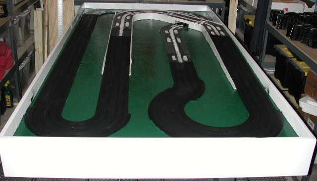
The picture above shows the lower portion of the track that has been filled, sanded and painted. The upper half has Vinyl Spackling Compound applied, but has not yet been sanded or painted.
Note too that the outsides of all of the turns have been wrapped with my HO Track Borders before I painted the track surface. These borders are made from Black Neoprene Rubber and are exactly the same height as the track surface itself. They create a nice wide apron to allow the rear end of a car to drift out onto the apron without falling off of the edge of the track.
In the photograph above you can see that I also painted the primed Homasote a dark green color. Rustoleum Hunter Green Glossy Enamel was used. Painting in between the mounted track sections was a tedious process, and if I were to do it over again I would paint the entire table top dark green before I fastened the track down. I would also have painted the inside edge of the retaining wall a Sky Blue color to avoid having to cut it in later once the track was attached.
In a latter phase Woodland Scenics Turf material will be applied to the green painted portions of the table. Woodland Scenics recommends that there turf products be applied to a surface that has been painted a color similar to the turf material itself.
I also found that it would have been easier to fill and sand the entire track all at once instead of doing it in sections. The sanding dust gets everywhere, so sanding the entire track in one single session would have greatly reduced the cleanup.
The picture above shows the edge of the track painted the same Hunter Green color as the table. This was done to reduce the apparent thickness of the track surface when it’s mounted on the table top. Use a small artist’s paint brush and work slowly. Use a clean rag to immediately wipe off any green paint that gets onto the track surface. You only want to paint the edge of the track to make it appear more flush with the table top.
Once the painted track has completely dried the metal power rails can be exposed. Using a small flat-bladed screwdriver, place the blade on a power rail and slowing scrape the paint for the top of the metal rail. Work slowly and pull the blade towards you as you work. Only remove the paint on the top of the rail, do not remove the paint on the sides of the steel power rails.
The power rails will not be as visible if only the top surface is exposed. With standard unpainted track light is reflected off the sides of the rail, making them much more predominate, but when only the top of the rail is exposed the rails are much more difficult to see and add to the overall realism of the raceway. The flat black paint that was used to cover the track surface also serves to absorb light that would otherwise be reflected off of the shiny metal rails.
Painting the Track Aprons
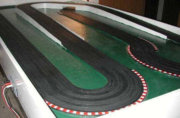
The picture below illustrates FISA curb striping applied to the outside of a turn. After applying my HO Track Borders the aprons were painted white. When the white paint had dried 3M ½” Blue Painters Tape was applied to create an alternating pattern. The exposed areas were then painted red.
The end result is a very attractive striped curb that is the same height as the actual track surface. Using my HO Track Borders eliminates the need for guard rails and allows a car in the outside lane to slide out and not fall off the edge of the track.
With the construction phase completed I was able to move the table into my racing room. The remaining landscaping elements and trackside buildings can now be installed in my hobby room instead of my shop.
FISA Track Apron Tape
The picture below illustrates my HO Turn Borders with FISA Curbing Tape applied instead of painting them. The FISA Curb Tape Kit includes White Vinyl Tape that is applied directly to the Turn Borders. The kit also includes ½” Square Die-Cut Red Stripes that are applied at ½” intervals to create a FISA-style apron at the outside of each turn.
If you would prefer to not have to paint your track aprons then my FISA Curb Tape Kit is an ideal alternative. It only took me about 45 minutes to do the entire track as shown above. The overall effect of filled, sanded and painted track in combination with the FISA curbing adds to the realism of the layout.