
Modern AFX and Tyco slot car motors require a power supply producing 18 to 20 volts of direct current (VDC), while older Model Motoring cars require 20 to 24 VDC. The wall-outlet power pack supplied with most boxed racing sets is not sufficient for use on large table-mounted racing layouts.
DC power supplies normally have two specifications, the output voltage and the output current. Modern HO slot car motors require at least 18 VDC, and 1 ampere or more of current for proper operation. Most of the DC power supplies currently being manufactured provide only 12 to 13.8 VDC. These WILL NOT work for HO slot car tracks. They will however work properly for larger 1:32 and 1:24 scale slot car tracks.
A good quality DC power supply is essential to safe, trouble-free racing and prolonged motor life. Investing in a good power supply will quickly pay for itself in motor savings alone.
A good rule of thumb to use when determining the size of the power supply required is to multiply the number of lanes by 1 ampere or more. Especially long layouts or very hot motor armatures may require more power, but 1-2 amperes per lane should be sufficient for all but the most demanding racing situations.
A 5-10 ampere DC power supply would be a good choice for a long 4-lane racing layout. This should provide sufficient power with an adequate reserve.
Power needs to be applied evenly around the entire race track. Slot car tracks with lane lengths greater than about 20-25 feet will need to have power applied at several locations. The rail connections at the joints in plastic sectional track are the single largest factor contributing to voltage drops as the cars move farther and farther away from the power terminal track.
It is often said that power should be applied every 15 or 20 feet for an even power distribution. This is true, but an even better way of determining power terminal track spacing is to count track joints. It is the joints that rob your track of power not just the length. Applying power every 12 to 15 track joints will assure that your track is properly powered.
It is important to determine where power will be applied before you build your track and mount it permanently to a table. Racers who skimp on adequate track power distribution will be disappointed when they have completed their track and find that cars slow dramatically on those sections of the race track farthest from the power taps.
Replacing the power supply with a unit producing higher amperage has very little effect on power distribution. Inadequate power distribution produces voltage drops around the circuit. All of the amps in the world can’t overcome this drop in voltage though.
Powering each lane with 1 or 2 amperes is sufficient if power is distributed evenly. It’s far more important to apply track power evenly around the racing circuit than it is to have a high-output power supply feeding a single set of power terminal tracks. Regardless of the power supply output, cars will slow down dramatically as they travel farther away from the power source.
Generally speaking, a 4-lane race track mounted on a 4×8 foot table would require 2 or 3 power taps, while a 4×12 foot table would probably require at least 4 or 5 taps. Even larger and longer race tracks may need as many as 10 power taps. Count the joints for a single lane and then divide by 12 or 15 to get a better idea as to how many power taps your particular track design requires.
Commercial HO Power Supplies
Astron is a good source of high quality DC power supplies for HO slot car racing layouts. Astron offers several nice 0-30 Volt Variable DC Power Supply models producing 10 amperes of power or more. Astron power supplies are fully regulated. A regulated power supply eliminates power surges associated with other multi-lane power supplies.
A large voltmeter and ammeter on the front panel show the current output power status. Output voltage is adjustable from 0-30 VDC. Modern HO slot car motors run at 18 VDC, but with an adjustable power supply you can also reduce the voltage when young racers or novices are running.
Older Aurora T-Jets like slightly higher voltages around 20-22 VDC, so an adjustable power supply is ideal here too. Higher voltages equate to faster speeds, but also hotter motors, so it’s always a good idea to stay within the recommended voltage range for the type of slot cars being raced.
I’ve sold other less capable power supplies over the years, but now I stock only the best. A good power supply is a big investment. Don’t waste your time and money on lower-priced units that burn up and can’t be easily repaired. Some of the junk sold on eBay is just that junk.
Three different HO Power Supply Models are available:
The Astron Series of DC power supplies listed above all have 0-30 VDC variable voltage outputs as well as adjustable current output ranging from 1.5 amperes to the full load rating.
A variable voltage DC power supply will also allow you to reduce the voltage when young or inexperienced racers drive your cars. Reducing the voltage to 9-12 VDC will make it much easier for very young children to race without having the cars constantly flying off the track. As their car handling skills improve you can increase the voltage gradually until they are using the full 18-20 VDC that modern HO tracks normally use.
If you’re considering a high-current power supply then I’d recommend the 35 Amp unit listed above over the 25 Amp model. The 35 Amp model costs only $50.00 more than the 25 Amp unit, yet delivers a full 10 amperes more of current.
Commercial 1:32 Scale Power Supplies
I also carry the full line of Aston 0-15 VDC adjustable power supplies for 1:32 scale racing. These lower voltage 0-15 VDC units are for 1:32 Scale Racing ONLY! Do not attempt to use these lower voltage units with HO scale slot cars or you’ll be very disappointed. HO slot car motor require higher voltages than these units provide.
These models all have dual meters for voltage and amperage just like the HO models described above, but their output voltage is adjustable from 0-15 VDC.
These 0-15 VDC power supplies listed above are for 1:32 Scale Racing ONLY!. For high-quality power supplies suitable for HO scale racing see the Commercial HO Power Supplies listed above these units.
Custom Power Supply
If you feel comfortable building your own electronics projects you can easily make the DC power supply illustrated below for under $25 dollars per lane.
If you would like to provide individual power supplies for each lane of your race track this simple design will produce 3.5 amperes per lane. This power supply would be ideal for large layouts or HO Slot Cars using hot armatures.
This power supply design uses only three (3) components available from Radio Shack’s web site or your local Electronics Parts Store.
Parts Required
- T1 – 16 Volt – 3.5A CT Transformer
- D1 – 50 Volt – 10A Full Wave Rectifier
- C1 – 2200 uF – 35V Electrolytic Capacitor
A 4-lane power supply using four (4) of each of the components listed above will cost you less than $100.00, yet will provide 3.5 amperes per lane, for a total power output of nearly 15 amperes.
This power supply design uses a classic full wave diode bridge circuit (D1) to rectify the transformer’s secondary AC output (T1). The capacitor (C1) smoothes DC ripple.
The instructions and schematic for building your own custom power supply have intentionally been left rather vague. If you’re comfortable working with the 120 VAC primary side of the transformer, or know someone who is, perhaps a HAM radio operator, then this would be a simple one-evening project. Due to the high voltage primary wiring on the transformer this project should only be undertaken by someone who understands what they’re doing. This is NOT a good first project for the electronics novice!
Power Requirements
The table below shows the maximum peak current (amps) drawn by various types of HO slot car motors.

Track Wiring
Neat track wiring is important. Spend the extra time to properly wire your slot car racing layout. Solder all connections whenever possible, or use crimp-on connectors if you do not want to solder. Use 14 of 16 gauge stranded wire for all power, controller and track connections. The increased wire gauge will guarantee safe racing.
The diagram below illustrates the basic track wiring required for a single lane. Expand this for the number of lanes your racing layout has.
A 2 ampere fuse should be sufficient to protect your car and controller. If you run hotter motor armatures you may need to increase the fuse rating to 3-5 amperes. Each lane should be individually fused. Do not use a single fuse for all lanes.
If your controllers do not include a brake circuit the red wire at the drivers stations will be unused. It’s always a good idea to wire your track for brakes even if you don’t plan to use controllers with brakes initially. Re-wiring for brakes can be a real headache later on. It costs next to nothing to provide the brake circuit right from the start.
See the Construction section of this web site for step-by-step pictures of a 4-lane raceway being built and wired using the wiring schematics below.
The diagram below illustrates typical 4-lane wiring using standard dual-row barrier terminal blocks for all power, controller and track connections. This wiring method uses solderless crimp-on spade lugs for all barrier terminal connections.
Longer race tracks will require power to be applied at several locations around the racing circuit. The barrier terminal blocks on the right side of the diagram below illustrate a wiring scheme for a track with power applied at two individual points on the race track. You can add extra terminal blocks if you plan to apply power in more than two locations. The actual length of the wires between the track terminal blocks on the right side of the drawing will be longer than those illustrated below.
The 4-lane track wiring diagram shown above can be used with a single power supply or individual power supplies connected to each of the four lanes. If a single power supply is to be used bridge the four positive power lines (white wires) together with a jumper wire. Use a second jumper to bridge the four negative power lines (red wires) together as well.
Required 4-Lane Track Wiring Parts
- (3) – 8 Position Barrier Terminal Blocks
- (4) – 4 Position Barrier Terminal Blocks
- (48) – #6 Spade Lug Terminals
- (50) – Feet of White 16 Gauge Wire
- (50) – Feet of Black 16 Gauge Wire
- (50) – Feet of Red 16 Gauge Wire
The wiring diagrams illustrated above assumes that power fuses are installed at each of the four driver’s stations. See the Track Wiring Supplies section at the end of this page to order these parts.
Track Wiring Kits
I sell 2, 4, 6 and 8-Lane Track Wiring Kits that come complete with Fused 3-Wire Drivers Stations for dynamic motor braking. These kits include everything required to wire a slot car track of any scale. No soldering or prior electrical experience is required. The step-by-step instructions are easy to follow.
The kits includes everything required to wire a 2, 4, 6 or 8-lane slot car track except the power tracks themselves. The kits provide enough materials for two (2) power tap locations. See the Power Tracks section listed farther down on this page to order Custom Power Tracks for any of the popular brands of HO and 1:32 scale track systems.
For a 2-lane track you’ll need to order two (2) Custom Power Tracks. For a 4-lane track you’ll need four.
If you have a large raceway and plan to have more than two power tap locations I also have 2, 4, 6 and 8-Lane Tap Expansion kits. These kits are designed to add extra power taps to the standard wiring kits. Each kit provides the additional supplies need to add one (1) power tap.
For 2-lane tracks order an additional power track for each extra power tap. For 4-lane tracks add two (2) more power tracks for each expansion kit. For 6- and 8-lane tracks, order three (3) or four (4) power tracks respectively.
Driver’s Stations
Simple and very functional driver’s stations can easily be made to allow racers to connect their hand controls. Purchase a 2×4 inch plastic project box from Radio Shack (Part No. 270-1802) for each lane. These boxes come with both a plastic and aluminum cover. Use the plastic cover and paint it to match the color of the lane it will control. Only the plastic cover is required, so save the aluminum cover and the lower section of the box itself for other projects.
Hand controls normally have black and white power wires and a red brake connection. You can purchase corresponding black, white and red banana jacks and plugs in the Track Wiring Supplies section at the end of this page.
Do not use the banana jacks and plugs sold at Radio Shack though as these are very poorly made and will not maintain a good electrical connection. Radio Shack does not offer a white banana plug or jack. It is very important that you maintain the red, white and black color scheme so as not to confuse racers.
The diagram below illustrates a single lane’s driver station. The banana jacks are mounted in 5/16 inch holes drilled on 1 inch centers.
If you have hand controls that will always be used with your race track install banana plugs on each of the three controller leads, maintaining the proper color coding.
If you would like to use alligator clips to connect your hand controls then remove the hoods from the banana plugs and just insert them in the jacks. These bare plugs will form posts that can be used to attach the alligator clips to.
If you mount banana plugs on some controllers and leave the alligator clips on other hand controls then purchase some extra banana plugs to use as posts when you want to use your hand controls with alligator clips.
If you want to add a power fuse at each driver’s station purchase a 2×6 inch project case instead (Cat No. 270-1804). The additional length will allow enough room for its mounting.
See the Construction section of this web site for pictures of Fused 3-Wire Driver’s Stations being installed in a 4-lane raceway.
If you would prefer to purchase ready-made driver’s stations instead of building your own I offer both fused and standard models. I highly recommend that you purchase the Fused version though. It’s much easier and less expensive to replace a 50 cent fuse than it is to replace a burned out power resistor in a hand control. Fuses at the drivers stations will also protect your track itself against potentially high current shorts.
My drivers stations come complete with CNC-machined white ABS plastic drivers station panels. These panels are much stronger than the Radio Shack project box covers and can easily be painted to match your tracks’ lane colors.
Each kit includes a CNC-Machined driver station panel, both Banana Jacks and Plugs in the correct Red, White and Black color codes and all wire leads with soldered spade lugs pre-installed. A 4-Position Barrier Terminal Block is also included for simple connections to the power supply and track. Fused stations include a Panel Fuse Holder and two (2) 3 Ampere fuses (1 as a spare.)
These are first rate drivers stations that look great and perform well. If you want to add the professional appearance of high-quality drivers stations to your raceway, then these are the ones for you.
Keep in mind though, that if you’re purchasing a Fused Track Wiring Kit you’re already getting Fused 3-Wire Drivers Stations, so you don’t need to order them separately.
Power Terminal Tracks
Power terminal tracks from Tyco and Tomy are expensive and will not allow you to use individual power supplies for each lane. Longer layouts need to have power applied at several locations on the layout. Using manufactured power terminal tracks can become quite costly.
This section describes a method of making your own power terminal tracks from standard straight track sections.
Making your own power terminal tracks is quite easy. All you will need is a soldering iron, soldering flux for electronics, and some rosin-core electrical solder. You will also need some short lengths of 16-18 gauge connection wire.
Note: The information provided here can also be used to attach wires to dead track sections used for electronic lap counters.
Start by placing a straight section of slot car track upside down on a towel dampened with cold tap water. The damp towel will prevent heat from the soldering iron being transferred to the plastic track.
The metal power rails running along each side of the guide pin slot are secured to the plastic track itself at 3 inch intervals. Locate a pair of these mounting points midway down the length of the straight track section and place a small dab of soldering flux on the exposed metal rail mounting points.
Cut two 12 inch lengths of hook-up wire and strip away 1/4″ of the insulation from one end of each wire. With a hot soldering iron heat the exposed wire and apply a small amount of solder to the heated wire. This tinning process will make later attachment to the metal power rails much easier.
Place one of the tinned hook-up wires at the point on the metal power rail where you had previously applied soldering flux and hold your soldering iron on the joint. Apply a small amount of additional solder once the flux begins to boil, and then carefully removed the soldering iron. Let the solder cool naturally, do not blow on the heated solder though, as this may fracture the soldered joint you just made.
Repeat the process described above for the remaining three metal power rails on a two-lane section of plastic slot car track.
Longer slot car tracks will require power terminal tracks placed at intervals around the circuit. The running length of track between power terminals is not nearly as important as the number of track joints separating the power terminals. The track joints themselves are the largest source of electrical resistance. A good rule of thumb is to use a power terminal track for every 12-15 track sections.
See the Construction section of this web site for pictures of power terminal tracks being installed in a 4-lane raceway.
If your slot car track employs a dead track section for an electronic lap counter use two power terminal track sections, one before and one after the dead section.
If you would prefer to purchase power terminal tracks made using the process described above see the price list below.
HO Custom Power Tracks
Aurora Model Motoring Power Tracks
Aurora Model Motoring track owners can use standard Aurora MM 9″ Terminal Tracks instead of my custom power tracks to wire older Lock & Joiner style tracks.
These New Old Stock (NOS) power terminal tracks are the original Aurora MM power tracks with 4 screw terminals molded at the side of each section.
These terminal tracks when used with my Fused Wiring Kits provide a simple means of wiring any older Model Motoring layout.
I often receive email from web site visitors asking how to wire their vintage Model Motoring tracks using the original set’s power pack and steering wheel controls. The diagram shown below should help those of you who have lost your set’s instruction booklet.

1:32 Custom Power Tracks
Tomy AFX 2-Lane Dual Power
2-Lane Tomy AFX track owners can easily configure their tracks to use individually powered lanes by simply adding a second Tomy AFX power terminal track and power pack.
The diagram below illustrates how to wire any Tomy AFX 2-lane race track to use individually powered lanes. This method will effectively double the power available to each car, and eliminate the power surge problems associated with a single power supply.
Simply insert a second Tomy AFX power terminal track into the layout with the connection block exiting from the same side of the track as the first one. Then connect one power pack and one hand control to each power terminal track. Each hand control needs to be connected to the corresponding lane it will regulate.
The diagram above shows two power terminal tracks placed next to one another for simplicity, but they can actually be placed anywhere around the raceway to allow the two drivers stations to be located at different points around a larger table.
Tomy AFX 4-Lane Quad Power
4-Lane Tomy AFX track owners can easily configure their tracks to use individually powered lanes by simply adding two additional Tomy AFX power terminal tracks and power packs as illustrated below.
Track Power Testing
Nothing is more frustrating than racing on a slot car track with corroded or loose power rail connections. Here is a simple and fool-proof method of locating bad track joints.
Start by first removing the last track section before the power terminal track and then slowly drive a car around the track until it stops. Whenever the car stops inspect and clean the power rail joints at the track section just before the loss of power occurred. Repeat this process for all lanes until the car travels around the entire circuit without slowing or stopping.
Finish up by replacing the last section of track and now you’ll have a race track without any power losses.
Track Wiring Supplies
Along with selling complete turn-key Track Wiring Kits and Drivers Stations I also sell all of the individual components needed to wire any scale slot car track professionally and safely.
All of the components I sell are top-quality prime parts. They’re U.S. made by well known electronics suppliers such as 3M, Cinch and Amphenol. Unlike the cheap parts Radio Shack is selling these days, these parts are high-quality, yet cost no more than what Radio Shack charges for their inferior foreign made stuff.
The adapters below have a banana jack molded to an alligator clip. They’re used for converting controllers with banana plugs to alligator clips. Each set of three (3) includes a Red, White and Black adapter.
STrak 8-Conductor plugs and jacks make ideal connectors for power wiring that spans multiple tables, or when drivers stations are mounted in their own free-standing enclosure.
These 8-conductor plugs and jacks are perfect for 4-lane track wiring looms and power inputs. Each pin is rated at a full 10 amps for safe, neat and attractive track wiring projects.
Panel Meters
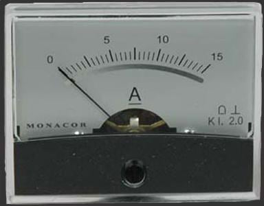
Metering track voltage and current is a good way to monitor power supply performance. Mounting a pair of these meters near the drivers stations allows racers to view track power while racing.
All of the panel meters listed below are 2-3/8″ wide × 1-3/8″ high and require a 1-1/4″ diameter mounting hole. The mirrored scale provides accurate readings at any viewing angle.
Track Braid & Copper Tape
I also stock braid and copper tape for 1:32 and 1:24 scale routed wooden track construction. If you’re building a wooden track these hard-to-find items are essential.